APPLICATION AREA
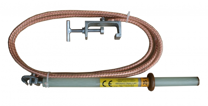
UT traction wire to rail bonding devices are designed for making protective connections between traction wires and running rails at mining operations and other plants where electric traction networks for 250 to 660 VDC voltages are deployed.
Two types of bonding devices are manufactured:
APPLICATION CONDITIONS
UT appliances for bonding of traction wire sections to rails are suitable for working areas of underground operations without the hazard of methane explosion and the ones with the ‘a’ degree of methane explosion hazard as well as with the ‘A’ class of coal dust explosion hazard.
TECHNICAL CHARACTERISTICS
The UT traction wire to rail bonding device is made up of the following components:
Stationary bonding devices are not provided with a clamping terminal for running rails and must be permanently
screwed to crossbars of floor tracks at the beginning and at the end of stations or warehouse areas.
CONFORMITY WITH STANDARDS
UT traction wire to rail bonding devices are manufactured in line with rules of good engineering practice in the field of occupational safety as well as current state-of-art in technical expertise with consideration to applicable technical standards and the 2014/35/UE Low-Voltage Directive.
TECHNICAL PARAMETERS
|
Bonding device type
|
Rated DC
voltage [V] |
Rated
one-second current [kA] |
Length of
bonding conductor [m] |
Cross-section
of bonding conductor [mm2] |
Weight
[kg] |
|
UT - 0,25/9/35/S(P)
|
250
|
9
|
3 ± 0.2 m
|
35
|
ca. 3
|
|
UT - 0,25/18,5/100/S(P)
|
250
|
9
|
3 ± 0.2 m
|
100
|
ca. 4
|
|
UT - 0,66/18,5/70/S(P)
|
660
|
18,5
|
3 ± 0.2 m
|
70
|
ca. 3,5
|
|
UT - 0,66/18,5/100/S(P)
|
660
|
18,5
|
3 ± 0.2 m
|
100
|
ca. 7
|