APPLICATION AREA
The K-20 relay is designed to continuously check continuity of the earthing line for various loads, e.g. a switchgear or a motor and to compare its resistance against the System of Earthing Safety Lines (SUPO). The relay can be operated in three-phase electric networks with the rated voltage of 500V and with an insulated neutral point of the supply transformer.
Contacts of interlocking modules or other components of control circuits can be incorporated into the measuring circuit which enables remote and voltagefree control of field devices.
DESIGN
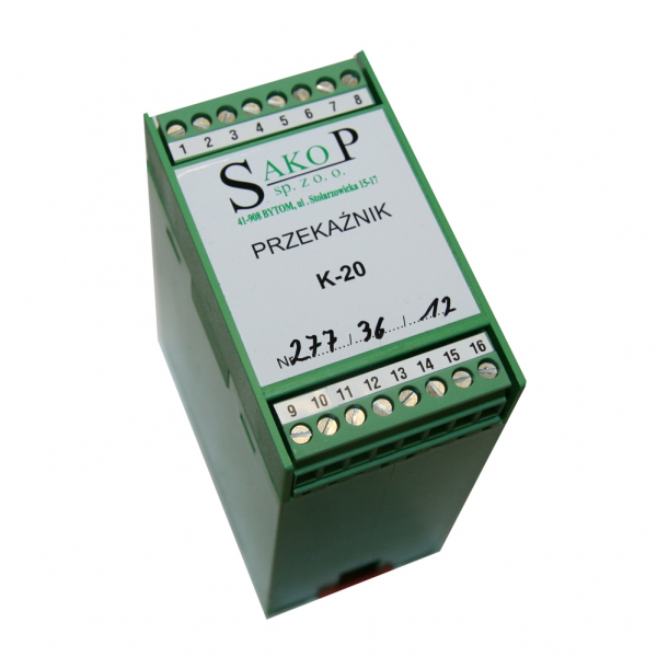
The K-20 relay for monitoring of earthing circuit continuity is encapsulated in an enclosure with the IP- 20 index of protection and suitable for mounting on the TS-35 DIN rail. The enclosure is provided with plugged connectors to communicate with the following circuits:
· Power supply 24V AC: terminal 6-7;
· Functional contacts: relay (toggle) type - terminals 1, 2, 3 and NO type – terminals 4, 5;
· Measuring inputs for monitoring of the earthing line condition: terminal 9 for the circuit of the auxiliary core of the power supply cable for the load and terminal 10 for the earthing line;
INSTALLATION
The relay is to be installed inside a control cabinet or box nearby the contactor switching the motor on and off. First, the relay enclosure is snap-on mounted on a standard top hat mounting rail of 35 mm size. Next, the relay must be connected to control circuits of the contactor according to the application diagram with use of LY-1.5...2.5 mm2 conductors (lug terminals must be squeezed beforehand on bare ends of connecting conductors).
COMMISSIONING
After having all connections completed in line with the application diagram please doublecheck correctness of the conductors routing and then supply the power voltage. Check of the device operability can be carried out by simulation of the situation when the resistance in the measuring circuit (between contacts 9 and 10) is increased to the level above 100 Ohm.
TECHNICAL PARAMETERS
· Rated power supply voltage 24 V AC
· Tripping resistance 80 Ohm ± 20%
· Reclosure resistance 60 Ohm ± 20%
· Tripping time < 100 ms
· Rated voltage across contacts 250 V AC
· Rated continuous current of contacts 6 A
· Rated switching frequency 600 cycles /h
· Rated insulation voltage 250 V AC
· Dimensions (W x H x D) 45 x 75 x 105 mm
· Index of protection IP 20